It feels a bit ironic to build a device with physical buttons to control stuff over Wi-Fi after having put effort into moving it to home-assistant to make them "smart", i.e. replacing physical switches with virtual ones.
Use case and requirements
The most used lights in my room are controlled via home-assistant. I keep a home-assistant tab open somewhere to click them on and off or resort to the mobile app on my phone when my PC is not on. I find both of that a bit cumbersome for just quickly switching of a light when leaving the room and decided to build a little macropad.
The requirements are quite simple:
- Enough buttons to control the most used devices
- Works when PC is off
- Buttons are easily reprogrammable in home-assistant
Hardware
At this point I'm sure I could find a good explanation why I specifically went with the Wemos D1 Mini for the project, the honest truth is that I had them lying around, they are cheap and do the job.
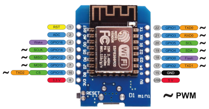
Six buttons seemed like a good amount, more than enough for the most used lights and not so many that I won't be able to remember which one does what. The Wemos D1 Mini has just about enough GPIO pins to accommodate for them, probably a few more if you really try.
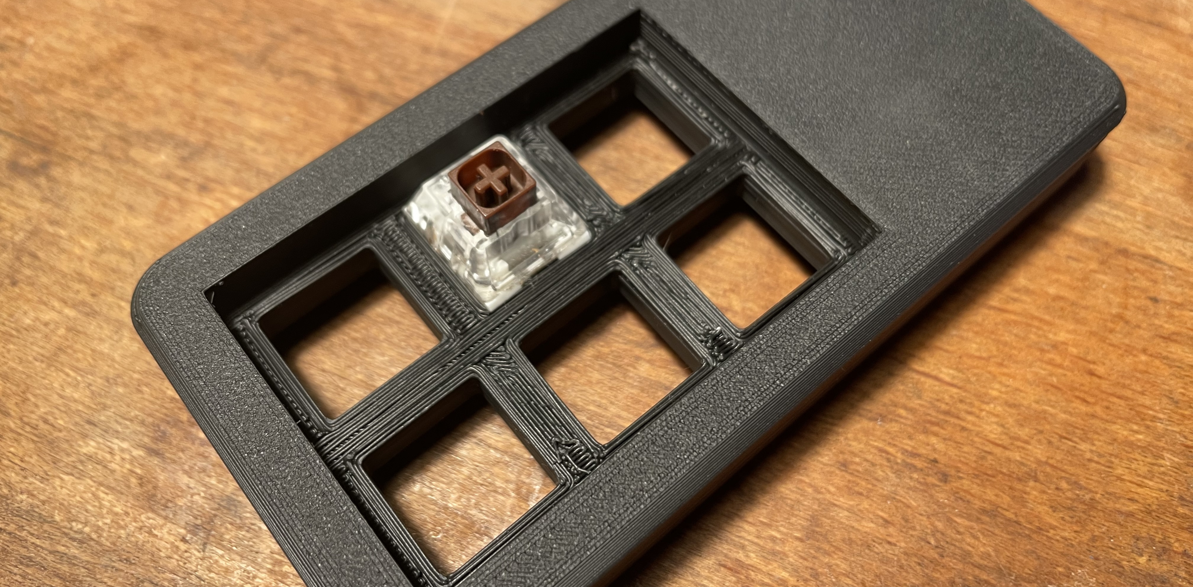
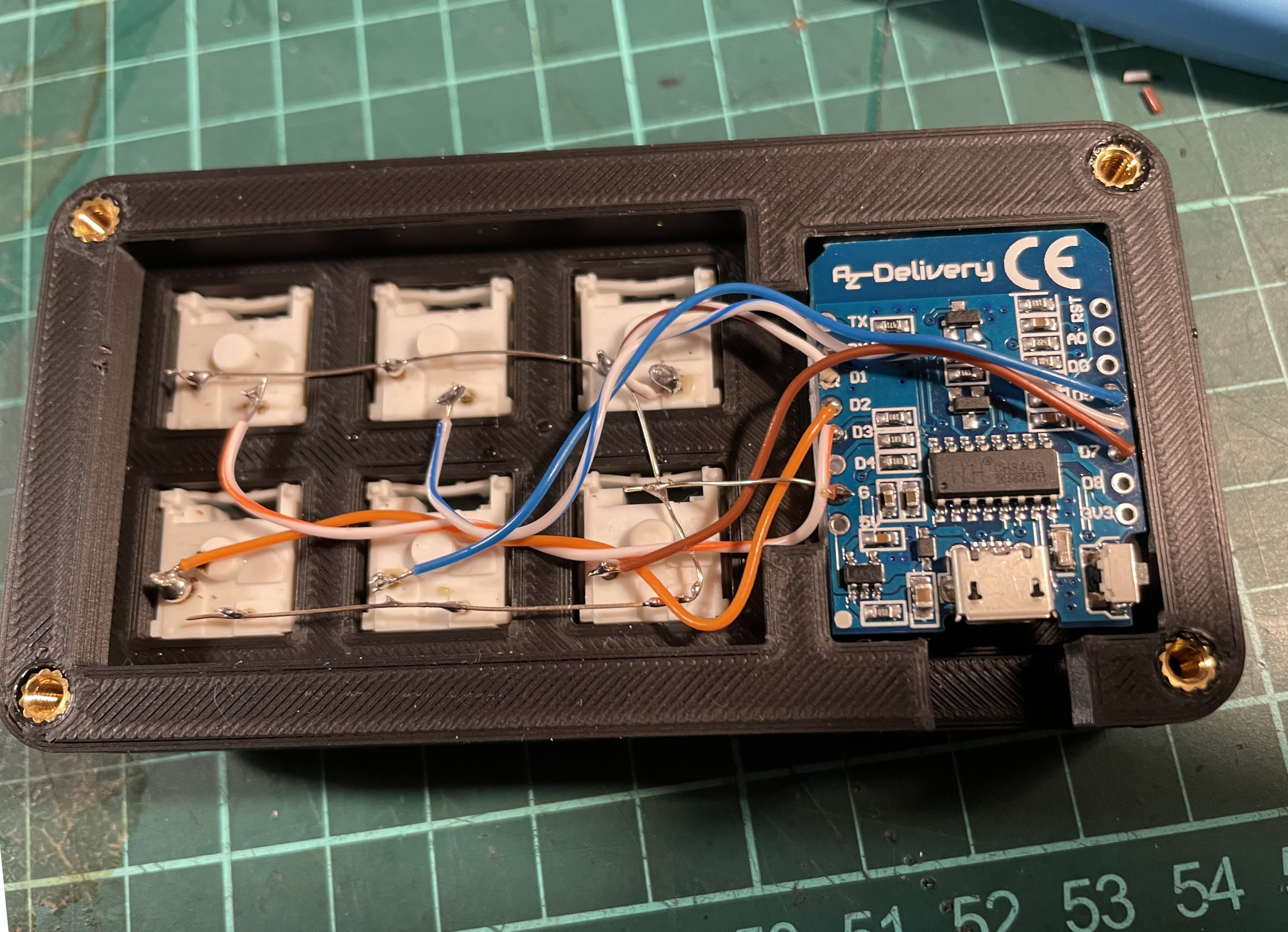
Nice feeling switches where easy: From building keyboards in the past I had more than enough spare cherry-style keyboard switches, as well as some blank DSA profile keycaps that would do nicely. This macropad uses Kailh brown box switches to be precise. Mounting and wiring is normally done on a PCB when building a keyboard, using diodes in a matrix pattern to save on pins. For six keys it is totally enough to just manually wire them to the GPIO pins and read the output. Instead of a mounting plate, the top half of the case will have fitting holes to press the switches in.
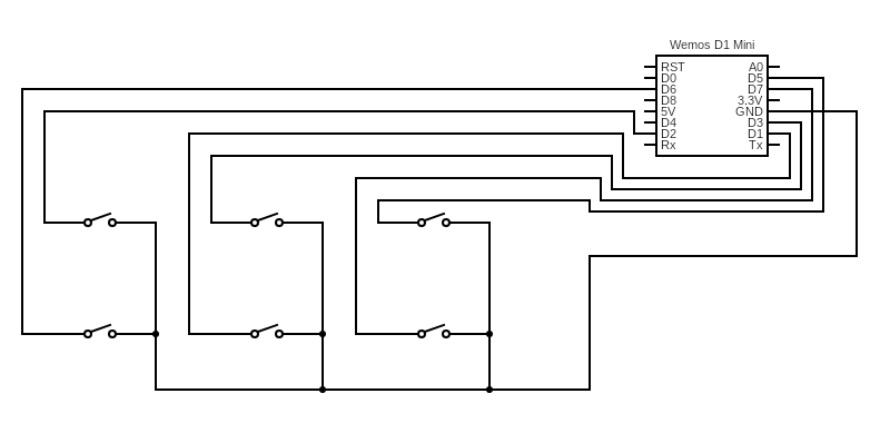
Each switch will be wired between a pin and a common ground connection. Not all the GPIO pins on the Wemos microcontroller have a pull-up resistor or work properly in this configuration, but I ended on this wiring diagram which does what you would expect.
Software
While you sure can write all the code for Wi-Fi, the switches and HTTP requests from scratch, esphome is a much easier way to implement this. I use it anyway on a number of devices and all that is needed to generate a firmware for the macropad is a bit of yaml. As a bonus, we get perfect integration in home-assistant, a Web UI and fallback hotspots if the connection fails among other features. Should I want to change the config later it can also be done over the air, which still feels a bit like magic to me.
Esphome config in Nix
As I slight twist, I'm doing my esphome configurations in nix instead of writing yaml for every device. It allows for simpler templating and reuse of config and also integrates better into the rest of my infrasturcture as it is also mosty defined as Nix code.
The trick is to have a flake, which defines packages for every device. Each package will contain a (generated) esphome configuration that can be flashed normally. This is my flake for this:
{
description = "esphome config files";
outputs = { self, nixpkgs }:
let
# System types to support.
supportedSystems = [ "x86_64-linux" "x86_64-darwin" "aarch64-linux" "aarch64-darwin" ];
# Helper function to generate an attrset '{ x86_64-linux = f "x86_64-linux"; ... }'.
forAllSystems = nixpkgs.lib.genAttrs supportedSystems;
# Nixpkgs instantiated for supported system types.
nixpkgsFor = forAllSystems (system: import nixpkgs { inherit system; });
in
{
# Packages for all files in ./configs
packages = forAllSystems (system: builtins.listToAttrs
(map
(file-name:
let
# Name package after the file, without suffix
name = builtins.head (builtins.split ".nix" file-name);
in
{
inherit name;
value = nixpkgsForsystemwriteTextFile {
inherit name;
text = builtins.toJSON ((import ./common.nix) // (import (./configs + "/file-name")));
};
})
(builtins.attrNames (builtins.readDir ./configs))));
};
}It defines a package for every file in the ./configs folder with the same
name. That folder will contain device specific configuration which is merged
with a common.nix file that has all common config like Wi-Fi settings,
logging and metrics, ports etc. The device-specific configuration for the
macropad in ./configs/esp-macropad.nix is simple:
let
device_name = "esp-macropad";
device_description = "ESP inside macropad";
in
{
esphome = {
name = device_name;
comment = device_description;
build_path = "/tmp/.esphome/build/device_name";
};
binary_sensor =
let
mode = {
input = "true";
pullup = "true";
};
platform = "gpio";
in
[
{ name = "Button 2"; pin.number = "D1"; pin = { inherit mode; }; inherit platform; }
{ name = "Button 6"; pin.number = "D2"; pin = { inherit mode; }; inherit platform; }
{ name = "Button 3"; pin.number = "D3"; pin = { mode.input = "true"; }; inherit platform; }
{ name = "Button 1"; pin.number = "D5"; pin = { inherit mode; }; inherit platform; }
{ name = "Button 4"; pin.number = "D6"; pin = { inherit mode; }; inherit platform; }
{ name = "Button 5"; pin.number = "D7"; pin = { inherit mode; }; inherit platform; }
];
}With this in place and the ESP connected via USB, the config is generated and flashed with two simple commands:
nix build '.#esp-macropad'
nix run 'nixpkgs#esphome' -- run result
Adding more devices is just a matter of placing the accordingly named files into
the ./config directory. esphome will compile the firmware and ask for the
interface to flash (or the IP address when flashing over the air).
As soon as the device is online, it can be adopted in home-assistant and used for automations as you would normally do.
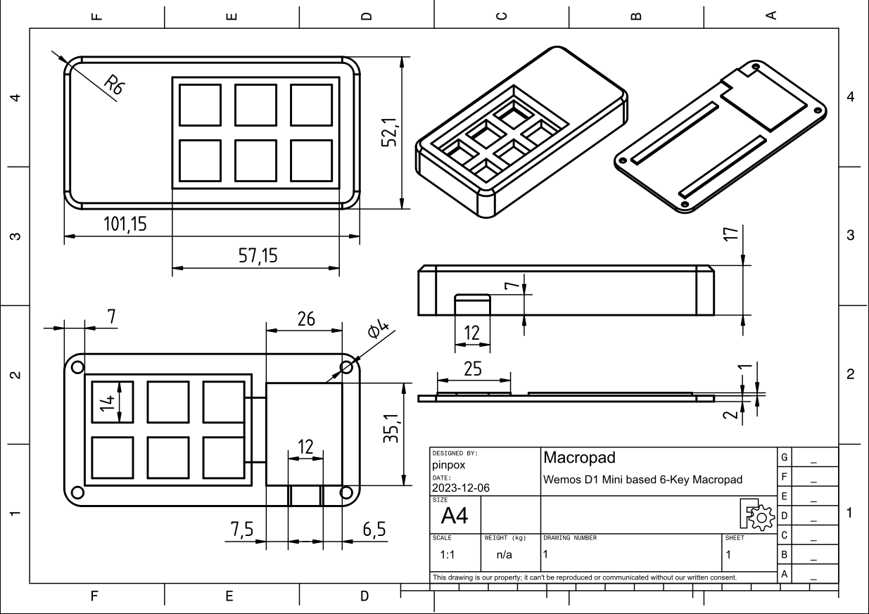
Case
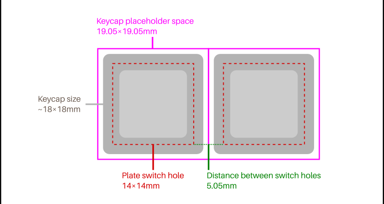
For the case the only constraints are that it should fit the cherry style switches and the microcontroller. For the switches I found this helpful diagram:
Using FreeCAD I settled on the following dimensions and design. The hole for the USB port was measured to fit a cable I had lying around with a reasonably sized plug. The holes are sized to fit M3 screw inserts that can be melted in with a soldering iron.
Assembly
The printed case fitted the switches nicely so that they won't fall out when pulling the keycaps without the need for any glue.
After pressing in the heat inserts and fitting all components, I wired one end of every switch together for a common ground and used isolated wires for each of the remaining contacts.
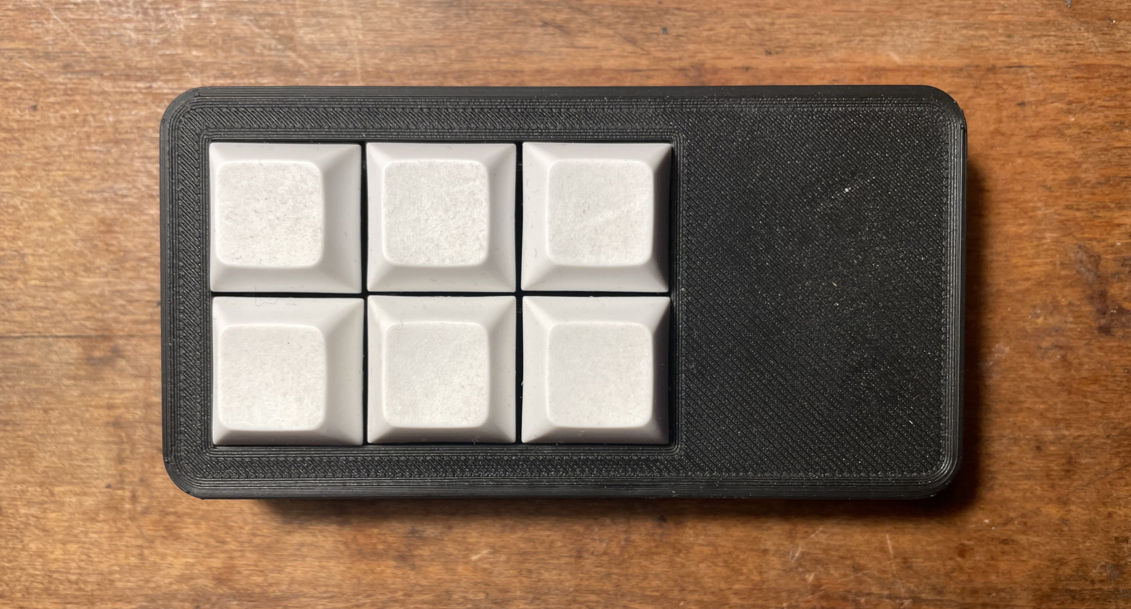
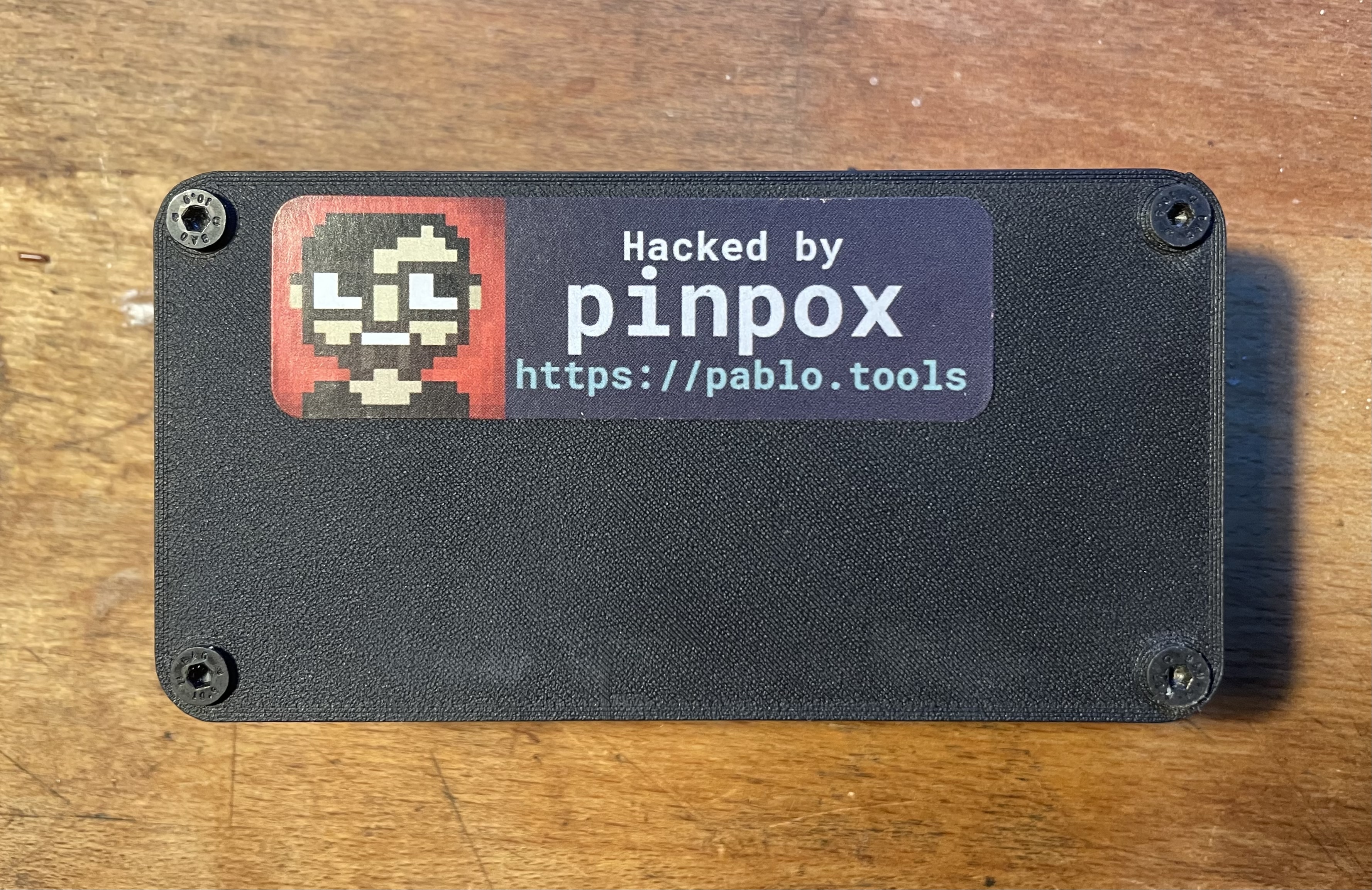
And that's pretty much it for the hardware! After a quick smoke-test I closed the case with M3-screews, pressed on some white DSA keycaps and added the obligatory sticker on the back.
The files for the case can be found here.